

 Current position > Product detail
『Flow Meter Control Valve Spacing: Modulating Flow Safely Without Creating Cavitation』Related information(v cone flow meter|rotary gas meter|gallon meter|gear meter|metal tube rotameter|glass tube rotameter|nutating disk meter|transit time ultrasonic flow meter|wedge flow meter|pd meters|hydraulic flow meter|ultrasonic water flow meter|water flow meter|air flow meter|magnetic water flow meter|oxygen flow meter|gas flow meter|argon flow meter|air velocity meter|gasoline flow meter|fuel flow meter|ultrasonic water meter|digital water meter|nitrogen flow meter|solid flow meter|Oxygen tank flow meter|digital water flow meter|diesel fuel flow meter|steam flow meter|02 flow meter|compressed air flow meter|oil flow meter|liquid flow meter)
Flow Meter Control Valve Spacing: Modulating Flow Safely Without Creating Cavitation
Quick Answer
Keep the control valve at least 10 pipe diameters upstream or 5 pipe diameters downstream of a flow meter for most liquid lines. For gas or steam, increase the downstream straight run to 15D or more. Cavitation forms when the control valve pressure drop forces liquid below its vapor pressure. Choose a flow meter location away from the valve vena contracta and add a backpressure valve if the liquid is near its boiling point.
Why Control Valve Spacing Changes Flow Meter Accuracy
A control valve creates turbulence, jet flow, and pressure pulses. Most flow meters need a stable velocity profile to measure correctly. An electromagnetic flow meter on a DN100 line may read 1 percent to 2 percent high if the control valve sits only 2D downstream. The same meter usually settles within 0.5 percent when the valve is 8D to 10D upstream. In practice, many contractors install the control valve too close because skid space is limited. We have seen this on water treatment skids in Malaysia and at fuel terminals in Singapore.
How Cavitation Forms in Liquid Flow Lines
Liquid accelerates through the narrow gap of a control valve. Pressure drops. If pressure falls below the vapor pressure of the liquid, vapor bubbles form. Downstream the pressure recovers and the bubbles collapse. The bubble collapse creates shock waves. The noise sounds like gravel moving through the pipe. The shock waves damage the valve trim and the pipe wall. A flow meter mounted close to this collapse zone sees noise, unstable readings, and in some cases physical damage.
Recommended Spacing for Flow Meters and Control Valves
Here is the thing. Most engineers skip this part during layout. The control valve arrives late and the pipe fitters install it wherever it fits. But spacing rules are simple. For liquid lines smaller than DN150, place the control valve 10D to 15D upstream of the flow meter. If the valve must sit downstream, give 5D to 10D after the valve before the flow meter. For gas and steam, use 15D to 20D downstream because the pressure recovery zone is longer. For slurry or high viscosity liquids above 100 cP, add a flow straightener or increase spacing by 50 percent. A globe valve creates a stronger jet than a butterfly valve. So add 5D extra downstream when a globe valve controls a low viscosity liquid.
Silver Instruments Models for Modulating Flow
Silver Instruments supplies flow meters for these loops. Electromagnetic flow meters work well for water, wastewater, and chemical dosing. They have no moving parts and handle 0.2 m/s to 15 m/s. Vortex flow meters suit steam and compressed air. Coriolis mass flow meters measure kg/
Real Field Example: Paint Manufacturer in Southeast Asia
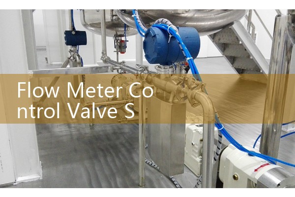
Last year a customer in Vietnam asked us about unstable readings on a DN50 oval gear flow meter. The meter was 1.2 meters after a globe control valve. Paint at 1200 cP flowed at 40 degrees Celsius. The pressure drop across the valve was 6 bar. The meter output jumped between 180 L/h and 340 L/h. We moved the flow meter to 15D downstream. We also added a back pressure valve set at 1.5 bar. The reading stabilized at 260 L/h with a variation under 1 percent.
How to Avoid Cavitation Without Oversizing the Valve
Do not accept a single high pressure drop across one control valve. Split the pressure drop over two valves or use a multi-stage trim. This fix is common in desalination plants in Saudi Arabia and Oman. Maintain downstream pressure at least 0.5 bar above vapor pressure for water at 25 degrees Celsius. For hot water above 80 degrees Celsius, increase that margin to 1 bar. Install the flow meter before the control valve when the liquid is near its boiling point. So the meter sees liquid, not vapor. But many skid builders do not leave this space.
FAQ: Flow Meter Control Valve Spacing
What is the minimum spacing between a flow meter and a control valve?
Use 10D upstream and 5D downstream for liquid lines. For gas or steam use 15D or more downstream.
Can cavitation damage a flow meter?
Yes. Cavitation bubble collapse can erode a meter liner, sensor body, or electrode. It also creates noise that corrupts the signal.
Which flow meter is best downstream of a control valve?
An electromagnetic flow meter or a Coriolis meter usually handles disturbed flow better than a vortex meter. Add straight run or a flow conditioner when space is tight.
How do I know if cavitation is present?
You hear a sound like gravel in the pipe. The flow signal may pulse. You may also see pitting on the valve trim during maintenance.
What information does Silver Instruments need for a quote?
Send us your fluid type, pressure in bar, temperature in degrees Celsius, pipe size in DN, flow range, and the valve type. We will reply with a recommended flow meter model and spacing layout.
Contact Silver Automation Instruments for flow meter selection and control valve spacing support. Tel: +86-135-1213-1526. WhatsApp: 86-135-12131526. WeChat: +86 13512131526.